Unit no 03: Digital Systems and Logic Designs
9TH CLASSLong Question Answers:
1. Explain the usage of Boolean functions in computers.
There are many uses of Boolean functions in the computers for various operations. Here are some examples of their usage:
- Arithmetic Operations: Boolean functions are used in Arithmetical Logic Units (ALUs) of CPUs to perform operations like addition, subtraction, multiplication, and even division.
- Data Processing: Boolean functions are used to process binary data in memory and storage devices, ensuring efficient data manipulation and retrieval.
- Decision Making: Boolean functions enable conditional operations, such as ‘If’ statements in programming. CPUs use Boolean logic to make decisions based on certain conditions (e.g., whether a value is zero or if two values are equal).
- Control Logic: Boolean functions are applied in computers to control various parts of the system’s operation to function in a coordinated manner.
Boolean functions are also present in our everyday devices like cell phones and calculators:
- Cell Phones: In cell phone processing, when you dial a number, or press a button on a phone, a Boolean function evaluates these inputs as true or false and makes the necessary output.
- Calculators: Basic calculators use Boolean functions. When you feed it with numbers and the operations to be performed, Boolean logic is used to arrive at the right result.
2. Describe how to construct a truth table for a Boolean expression with an example.
Boolean functions are algebraic statements that describe the relationship between binary variables and logical operations. These functions are particularly important for digital circuits, which are the basis of current computers, mobile phones and even simple calculator.
Understanding Boolean Functions:
A Boolean function is a function which has a one or more binary inputs and produces a single binary output. The inputs and outputs can only have two values: False (represented by 0) and True (represented by 1). The construction of Boolean functions is done by employing the basic logical operations such as AND, OR and NOT, which connect the inputs to generate the correct output.
Example 1: Simple Boolean Function
Consider a Boolean function with two inputs, A and B. We can construct a function F that represents the AND operation:
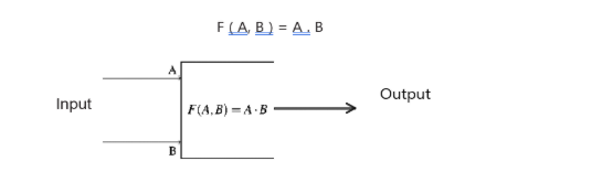
The diagram shown above demonstrates a basic digital circuit, which is an AND gate. The box symbolizes the AND function F (A, B) = A . B. This box has two inputs A and B. If both A and B are 1, the output will be 1. In any other case, the output will be 0. The input are shown at the entrance to the box, while the output is depicted at the exit of the block.
The truth table for this function is as follows:
| A | B | F(A, B) |
|---|---|---|
| 0 | 0 | 0 |
| 0 | 1 | 0 |
| 1 | 0 | 0 |
| 1 | 1 | 1 |
Example 2: Now, let us construct a more complex Boolean function with three inputs, A, B, and C:
let us construct a complex Boolean function with three inputs, A, B, and C:
F (A, B, C) = A . B + A . C
This function uses AND, OR and NOT at the same time. The truth table for this function is as follows:
| A | B | C | A.B | A | A.C | F(A, B, C) |
|---|---|---|---|---|---|---|
| 0 | 0 | 0 | 0 | 1 | 0 | 0 |
| 0 | 0 | 1 | 0 | 1 | 1 | 1 |
| 0 | 1 | 0 | 0 | 1 | 0 | 0 |
| 0 | 1 | 1 | 0 | 1 | 1 | 1 |
| 1 | 0 | 0 | 0 | 0 | 0 | 0 |
| 1 | 0 | 1 | 0 | 0 | 0 | 0 |
| 1 | 1 | 0 | 1 | 0 | 0 | 1 |
| 1 | 1 | 1 | 1 | 0 | 0 | 1 |
Explanation:
- The parameters A, B, and C are included in the following example as the input columns.
- The results of AND operation between two variable A and B are presented in the column A . B.
- The column A standing for the NOT operation of A.
- Every value in the column A . C displays the result of AND operation between the values in the Fifth column and the third column.
- The final column F (A, B, C) shows the output of the Boolean function (A . B) + (A . C)
3. Describe the concept of duality in Boolean algebra and provide an example to illustrate it.
Simplification of Boolean Functions
Simplification of Boolean functions is a particularly important process in designing an efficient digital circuit. Such simplified functions require fewer gates making them compact in size, energy efficient and faster than the complicated ones. Simplification means applying some Boolean algebra rules to make the functions less complicated.
Basic Boolean Algebra Rules:
Here is some fundamental Boolean algebra rules used for simplification:
- 1. Identity Laws A + 0 = A
A . 1 = A - 2. Null Laws A + 1 = 1
A . 0 = 0 - 3. Idempotent Laws A + A = A
A . A = A - 4. Complement Laws A + A = 1
A . A = 0 - 5. Commutative Laws A + B = B + A
A . B = B . A - 6. Associative Laws (A + B) + C = A + (B + C)
(A . B) . C = A . (B . C) - 7. Distributive Laws A . (B + C) = (A . B) + (A . C)
A + (B . C) = (A + B) . (A + C) - 8. Absorption Laws A + (A . B) = A
A . (A + B) = A - 9. De Morgan’s Theorems (A + B) = A . B
(A . B) = A + B - 10. Double Negation Law A = A
Simplification Examples
Simplify the expression A + A . B.
A + A . B = (A + A) (A+B) (Distributive Law)
= 1 . (A + B) (Complement Law)
= A + B (Identity Law)
Simplify the expression A . B + A . B.
A . B + A . B = A + B + A . B (De Morgan’s Theorem)
Since A is already present in
(A . B), we can use absorption law
ie A + (A . B) = A
= A + B
Simplify the expression (A + B) (A + B)
(A + B) (A + B) = A.(A + B) + B . (A + B) (Distributive Law)
= A . A + A . B + B . B (Absorption Law)
= A + A . B (Identity Law)
= A (1 + B) (Distributive Law)
= A . 1 (Null Law)
= A (Identity Law)
Simplify the expression A + B (A + B)
A + B (A + B) = (A . B) (A + B) (De Morgan’s Theorem)
= A . B . A + A . B . B (Distributive Law)
= A . B + A . B (Idempotent Law)
= A . B (Identity Law)
4. Compare and contrast half-adders and full-adders, including their truth tables, Boolean expressions, and circuit diagrams.
Digital logic is an essential aspect for the functioning of several modern electronic systems, such as computers, smart phones, and other digital gadgets. Digital logic optimizes in many ways to create and enhance circuits meant to perform various tasks. Two important applications of digital logic are the design of adder circuits and the use of Karnaugh maps for function simplification.
Half-adder and Full-adder Circuits
Adder circuits are widely used in digital circuits to perform arithmetic calculations. There are two general forms of adder circuits known as half-adders and full adders.
1. Half-adder Circuits
A half adder is a basic circuitry unit that performs addition of two single-bit binary digits. It has two inputs, usually denoted as A and B, and two outputs: the sum (S) and the carry (C).
Truth Table for Half-adder:
| A | B | Sum (S) | Carry (C) |
|---|---|---|---|
| 0 | 0 | 0 | 0 |
| 0 | 1 | 1 | 0 |
| 1 | 0 | 1 | 0 |
| 1 | 1 | 0 | 1 |
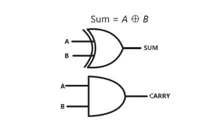
Boolean Expressions for Half-adder:
S = A ⊕ B C
= A . B
In this case the symbol ⊕ represents the XOR operation. The sum output is high when only one of the inputs is high, while the carry output is high when both inputs are high.
Boolean Expressions:
Full-adder Circuits
A full-adder is a more complex circuit that adds three single-bit binary numbers: two bits that belong to the sum and a carry bit from a previous addition. It has three inputs, denoted as A, B, and Cin (carry input), and two outputs: called the sum (S) and the carry (Cout) with both being integer values.
| A | B | Cin | Sum (S) | Carry (Cout) |
|---|---|---|---|---|
| 0 | 0 | 0 | 0 | 0 |
| 0 | 0 | 1 | 1 | 0 |
| 0 | 1 | 0 | 1 | 0 |
| 0 | 1 | 1 | 0 | 1 |
| 1 | 0 | 0 | 1 | 0 |
| 1 | 0 | 1 | 0 | 1 |
| 1 | 1 | 0 | 0 | 1 |
| 1 | 1 | 1 | 1 | 1 |
Boolean Expressions:
Sum = A ⊕ B ⊕ Cin
Carry = (A.B) + (Cin . (A ⊕ B))
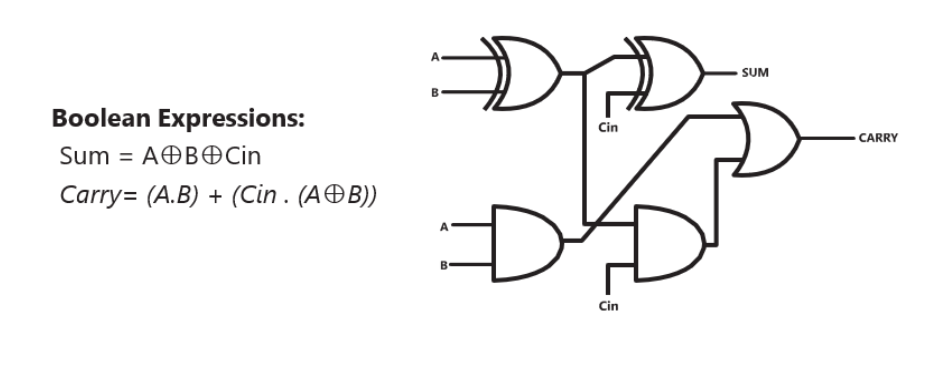
The sum output is high if the number of high inputs is odd whereas the carry output is high if the number of high inputs is at least 2.
5. How do Karnaugh maps simplify Boolean expressions? Provide a detailed example with steps.
A Karnaugh map (K-map) is a graphical representation which can be used to solve Boolean algebra expressions and minimize a logic function where algebraic computations are not employed. It is a technique in which the truth value of Boolean function is plotted to enable the identification of patterns and to perform term combining for simplification.
| Minterm | Variables Combination | Minterm Expression |
|---|---|---|
| m0 | A=0, B=0, C=0 | ABC |
| m1 | A=0, B=0, C=1 | ABC |
| m2 | A=0, B=1, C=0 | ABC |
| m3 | A=0, B=1, C=1 | ABC |
| m4 | A=1, B=0, C=0 | ABC |
| m5 | A=1, B=0, C=1 | ABC |
| m6 | A=1, B=1, C=0 | ABC |
| m7 | A=1, B=1, C=1 | ABC |
A K-map is a matrix where each square is a cell, which corresponds to a positioned combination. These cells are filled with ‘1’ or ‘0’ in reference to the truth table of the Boolean function. The size of the K-map depends on the number of variables:
- 2 Variables: 2×2 grid
- 3 Variables: 2×4 grid
- 4 Variables: 4×4 grid least
- 5 Variables: 4×8 grid (less common for manual simplification)
Every cell in the K-map represents a minterm, and the cells in each row of the K- map differ by only one bit at any particular position, following the gray code sequence.
6. Design a 4-bit binary adder using both half-adders and full-adders. Explain each step with truth tables, Boolean expressions, and circuit diagrams.
Half Adder Circuits:
A half adder is a basic circuitry unit that perform addition of two single-bit binary digits. It has two inputs, usually denoted as A and B, and two outputs: the sum S and the carry C.
Truth Table for Half Adder
| A | B | Sum (S) | Carry (C) |
|---|---|---|---|
| 0 | 0 | 0 | 0 |
| 0 | 1 | 1 | 0 |
| 1 | 0 | 1 | 0 |
| 1 | 1 | 0 | 1 |
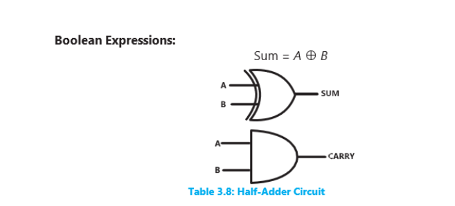
Boolean Expressions for Half-adder:
S = A ⊕ B C
= A . B
In this case the symbol ⊕ represents the XOR operation. The sum output is high when only one of the inputs is high, while the carry output is high when both inputs are high.
Boolean Expressions:
Full Adder Circuits:
A full-adder is a more complex circuit that adds three single-bit binary numbers: two bits that belong to the sum and a carry bit from a previous addition. It has three inputs, denoted as A, B, and Cin (carry input), and two outputs: called the sum (S) and the carry (Cout) with both being integer values.
| A | B | Cin | Sum (S) | Carry (Cout) |
|---|---|---|---|---|
| 0 | 0 | 0 | 0 | 0 |
| 0 | 0 | 1 | 1 | 0 |
| 0 | 1 | 0 | 1 | 0 |
| 0 | 1 | 1 | 0 | 1 |
| 1 | 0 | 0 | 1 | 0 |
| 1 | 0 | 1 | 0 | 1 |
| 1 | 1 | 0 | 0 | 1 |
| 1 | 1 | 1 | 1 | 1 |
Boolean Expression:
Sum = A ⊕ B ⊕ Cin
Carry = (A.B) + (Cin . (A ⊕ B))
The sum output is high if the number of high inputs is odd whereas the carry output is high if the number of high inputs is at least 2.
7. Simplify the following Boolean function using Boolean algebra rules: F (A, B) = A . B + A . B
B + 1 = 1 Null Law
F (A, B) = A . 1
F (A, B) = A Identity Law
F(A, B) = A Answer
8. Use De Morgan’s laws to simplify the following function: F (A, B, C) = A + B + AC
De-Morgan’s Law states:
A + B = A . B
A . B = A + B
F(A, B, C) = (A . B) + (A . C)
F(A, B, C) = A . B + A . C Answer
9. Simplify the following expressions:
(a) F = A + B . (A+B)
X . X = 0 Null Law
Using Complement Law
So, F=0
(b) (A+B) . (A+B)
F = A . A + A . B + B . A + B . B
A . A = 0 (Complement Law)
B . B = 0 (Complement Law)
F = 0 + A . B + B . A + 0
F = A . B + A . B
(c) A + A.(B+C)
F = A + (AB) + (AC) Distributive law
F = A + B + A.C Absorption Law
(d) A+B+A.B
(e) (A.B) + (A.B)
F = A ⊙ B
OR F = A ⊕ B